Light Sensor with Arduino for the Muni Sign
Contents
"SF Muni Sign at Home" series
Several post on how I was building a San Francisco Muni sign that shows train arrival times at home.- SF Muni LED Sign at Home with Raspberry Pi — first post where I introduced the sign;
- Light Sensor with Arduino for the Muni Sign — how to add light sensor to shut the sign off when it's dark.
- Tidbyt: Someone's making the Muni Sign — someone's Kickstarter project to make a similar art piece!
When I installed SF Muni sign in my apartment, I realized it had contradictory requirements when it comes to positioning. On one hand, I want it to be visible from my couch, where I sit in the morning. On the other hand, I would want it powered off when I sit on the very same spot in a darkened room, say, when I'm watching a movie. Manually turning it on and off (a custom remote control?) would undermine the whole idea of having a fully automated always-on sign. Installing an automated power on/off knob by itself is easy, but what would trigger it?
Note that powering the LED sign on and off was not a part of an official interface, but I resolved it by rendering an empty picture. I don't know how much energy it saves, but since the USB port is cold after a day of it being "powered off," I can guess that a lot.
I thought of using a schedule: say, power it in the morning, and power it off in the evening. That would probably do. This would be at indirect measurement, though. Schedule is not the problem here: the actual problem is the contrast between the lit sign and the background. What if I can measure the luminosity of the room directly? I have a computer that is much closer to hardware than what I used before, so why not install a light sensor?
Minus Pi
What we need is to somehow read the value of current ambient light, and transform it into digital form for our scripts to read. A light sensor is basically a diode that changes its resistance based on the outside light condition, and we need to read current that flows through its circuit. Unfortunately, the Raspberry Pi itself can not do this: it lacks digital-to-analog converter. Luckily for us, other small Pi-like computers do.
Arduino Nano

One of Arduino boards, Nano. I chose the smallest one that had analog input. There are more arduinos available.
Plus Arduino
One of the computers capable of this is Arduino. Unlike Pi, it does not run as a full-featured Linux machine. Instead, you load up a program from another computer, and Arduino then runs this program. Well, that's not too different from what happens on the Pi, but you definitely can't load Linux on small Arduinos.
So, since Light Sensor can't be connected to Pi, I bought Arduino Nano for $10. You probably can buy a different board (the important thing to look for is an "analog port",) but I bought the smallest because Pi is already large enough. The board I bought is, like, ten times smaller than Pi, and that's what I looked for.
Here's how it looks like, mounted:
Mounted Pi+Arduino+Sign
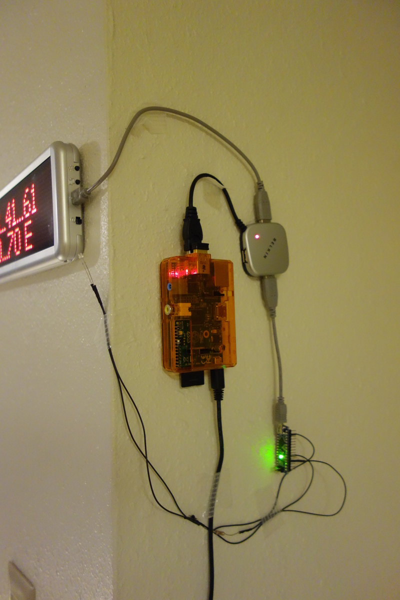
Here's how the whole thing looks on my wall when it's bright enough.
Circuit
Since my electronic circuitry skills are somewhere at high school Science classes level, I used this video as a guide. Here's the circuit that guy describes:
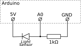
Please excuse my mad circuitry skills.
When the light is off
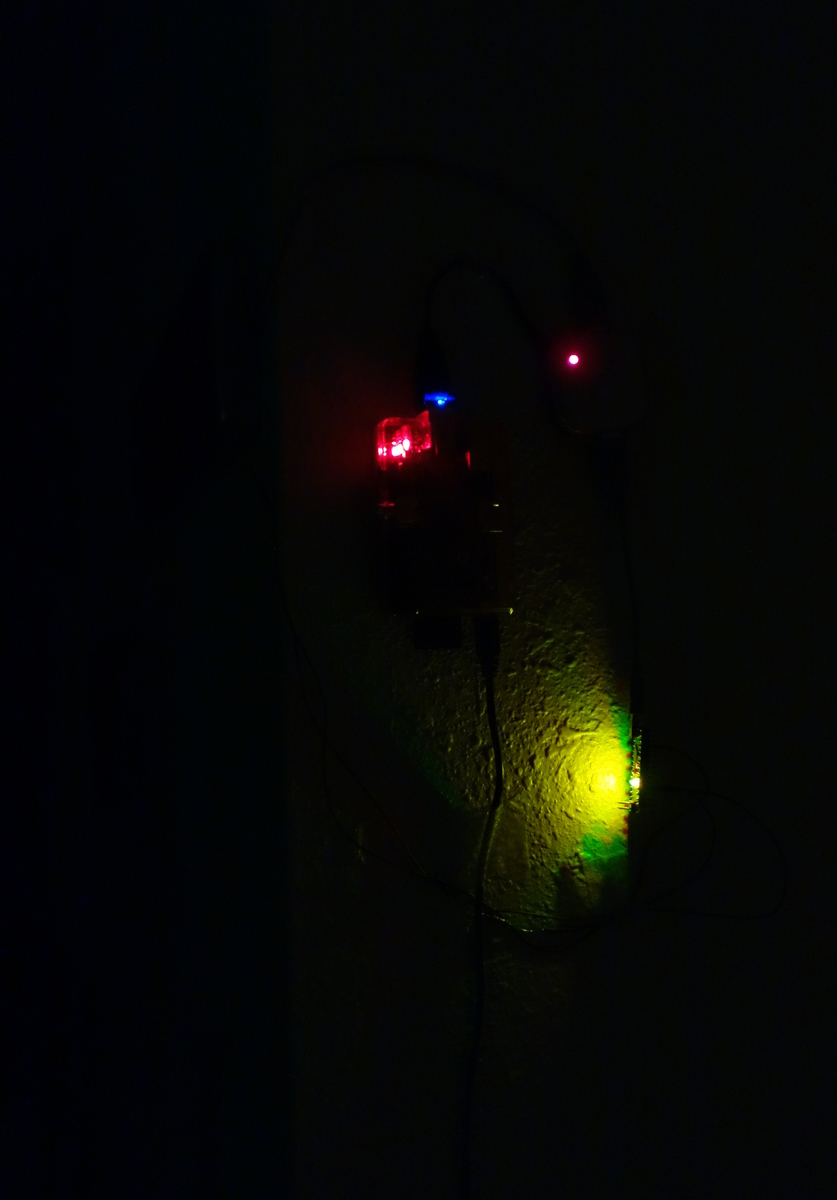
Note that the sign is shut off when there's no enough light. Fancy LEDs are conveniently hidden behind the corner, and don't face my couch. :-)
The components used are really cheap. Arduino itself cost $15. Light sensors and resistors (I used 1kOhm) are sold for five bucks a hundred, but I went for a more expensive option from RadioShack because the store is close to where I live. Since I don't know how to solder, I used female-to-female jumper wires to connect the components (I cut one wire's connector at one side with scissors to connect to the analog input A0.
Conclusion
So it worked as a charm. I played a bit with circuitry (see the notes below,) and can now watch TV without bright red LED lights imprinting on my retina. And I have a much weirder and colorful installation on my wall, which is by itself immensely cute as well as useful.
Programming notes
After I assembled the scheme, I proceeded to install SDK. I didn't try it on my desktop computer, and did this directly on Pi (because why borther?) The apt-get install arduino didn't work, and was showing some error I forgot to write down, but the advise I googled was to update first:
sudo apt-get upgrade && sudo apt-get update
sudo install arduino
Then I launched SDK from a remote console by typing arduino into my console (I made sure I ssh-ed with -X option, like ssh -X pi@192.168.100.100), and had the GUI pop up on my desktop while actually running on Pi. I pasted the program you can find in contrib, and pressed "Upload." It didn't work because I first had to select "Arduino Nano w/ATmega328" under "Tools -> Board" menu. This was all programming required: Arduino ran this program every time it was powered on, but I still needed to collect the digital data. The numbers were printed to the USB serial port, and I could read them either from Arduino SDK or by cat /dev/ttyUSB0 from a console.
This program only made sure that the numbers are printed onto the serial port, and a separate "collector" software that interacts with the sign client was still necessary. The collector script I wrote was communicating with muni sign program by creating a file, thus signaling that the sign should be shut down. I added another initscript and used rc-update to auto-start it.
When I first tried to check if the sensor works, I saw that it changes very abruptly with the luminosity. The value read 830-840 unless I completely shoved it under the cushion (where it read as 0). My physics intuition nudged me to decrease resistance, which I did, and achieved greater smoothiness. Now it could tell dimly lit room from a completely lit one, which was my original goal. I use threshold value of 100, but it will vary with resistor and the sensor you use. Oh, and light sensor is one-sided, so if the value you're reading is about zero no matter how bright the room is, you probably should insert it backwards.
I also couldn't find a way to assign ttyUSB ports, so that LED sign is always on /dev/ttyUSB0, and Arduino's serial port is always on /dev/ttyUSB1, and they get assigned randomly. I just reboot Pi a couple of times until it gets it.
That's all, and I hope this will help me reassemble it again.
I'd prefer using some kind of ADC (http://en.wikipedia.org/wiki/Analog-to-digital_converter) to measure analog signal level.